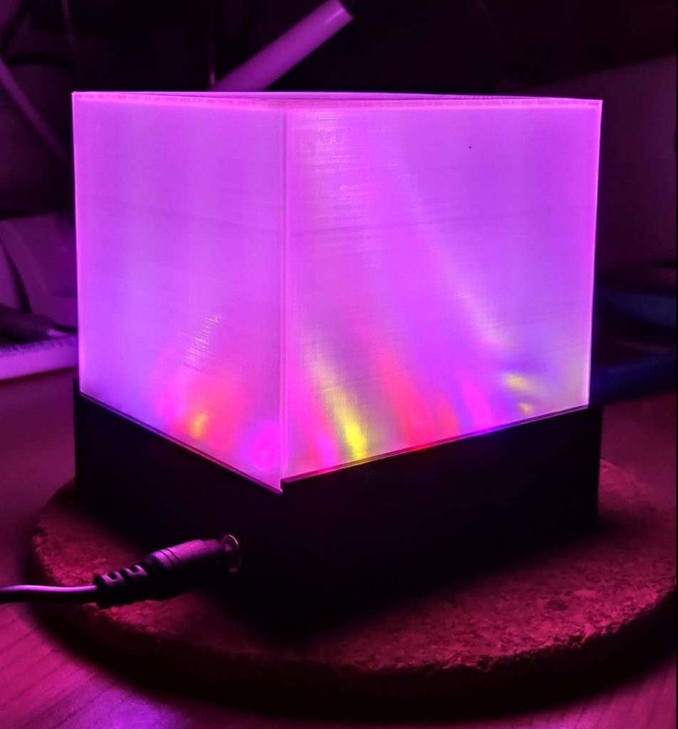
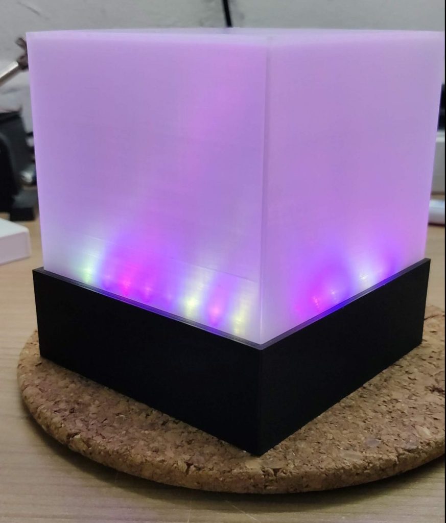
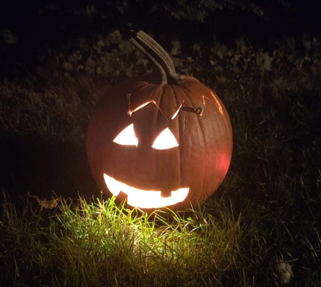
Recently we went out to carve some pumpkins for Halloween. After we finished our beautiful work my son asked me: “Dad, will they glow in the dark like my marmalade Lamp?”. My first answer was “no”, but then I thought, “Hey, why not 😄?” and on the same day I went to tinkercad to design a circuit.
The Idea
I wanted to have a light which turns on automatically when it dark outside. This light must be kinda watertight because it will be used outdoor inside a pumpkin and the circuit should be easy to build. I ended up with this circuit designed in tinkercad.
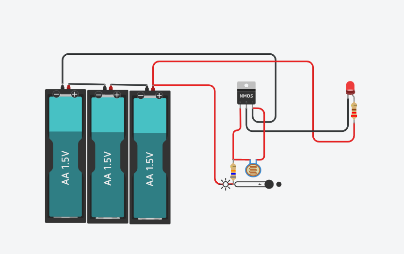
The circuit works as follows. The N-Channel MOSFET works as a switch. If the voltage on the gate (left pin) is higher than 2V, current can flow from the drain (center pin) to source (right pin). This turns on the LED. The gate is controlled by two resistors. One fixed value and one LDR which has a high resistance in the dark and a low resistance when its exposed to light. These two resistors form a voltage divider and control the voltage at the gate.
So during the day the resistance of the LDR is low which decrease the voltage at the gate and turns the MOSFET including the LED off. From dawn on the resistance of the LDR is getting higher which increases slowly the voltage at the gate. This also slowly turns on the MOSFET and the LED, perfect 😁.
In the real circuit I changed some parts because they weren’t available in tinkercad. The red LED incl. the dropping resistor will be replaced with an cheap white LED strip. The batteries will be replaced by an Li-ion battery incl. changing controller. Last not least I added a switch to the battery to turn everything off if its not in use for a longer time.
Parts list
For the automatic Halloween pumpkin light we will use the following components:
- Some hot glue
- Transparent heatshrink that fits over the LED strip
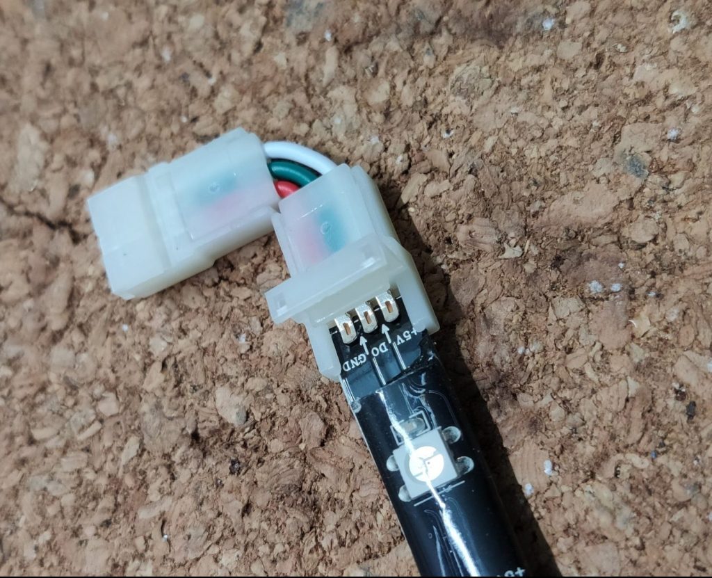
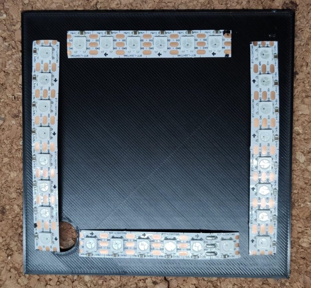
- Some cheap 5V LED strip
- Some wire
- A rechargeable Li-ion battery
- A switch
- An LDR
- An N-Channel MOSFET IRLZ44N
- A regular 86K resistor
- A USB-C type charging unit
- Some regular Heatshrink
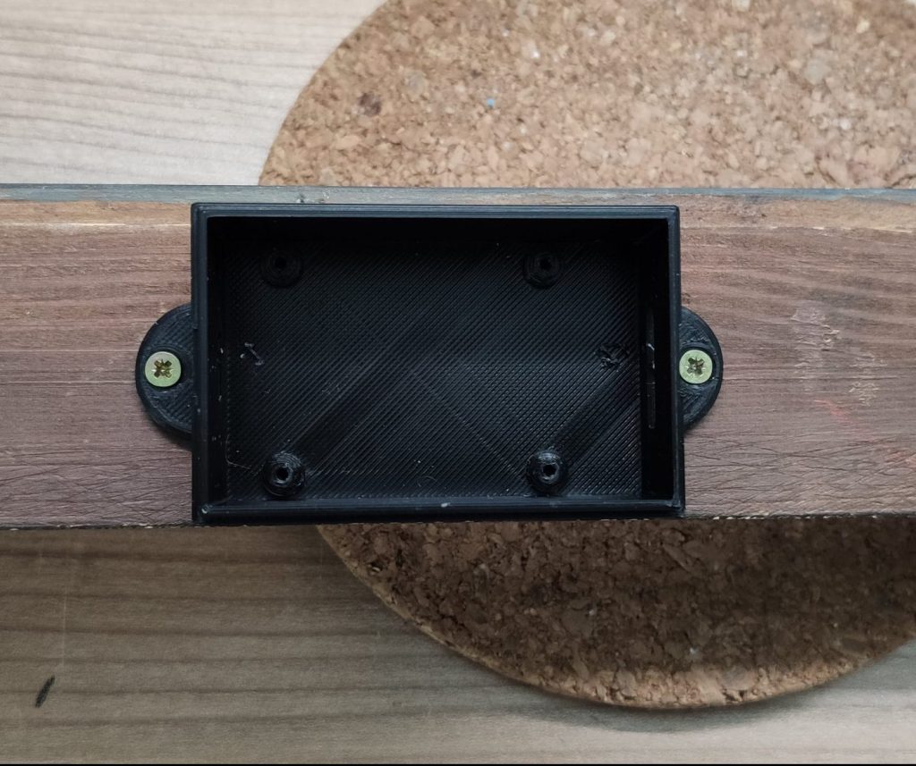
- An enclosure (I used a bubble gum pack)
*Some links are affiliate links. If you use them to buy the parts for your project you will help me and my next project. These links will cause no extra fees or costs to you

Breadboard time
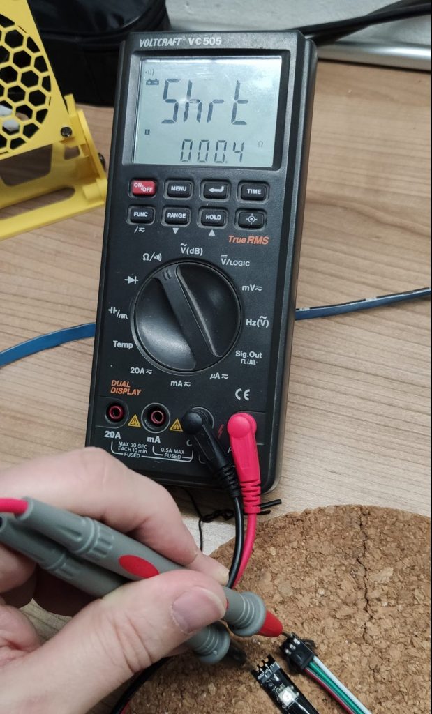
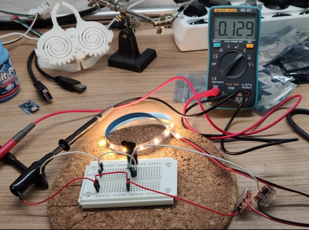
Before I fired up my soldering iron I hooked put together on a breadboard, because I wanted to know which resistor value works best for my LED strip and MOSFET. First I started with a 100K resistor but using that value the gate voltage was only 2.2 volts, if there was no light on the LDR. Because I wanted to have a higher voltage at the gate, to turn the MOSFET completely on, I went with an 86K resistor. That increases the voltage at the gate to about 2.9 volts which turns the MOSFET nearly complete on.
Besides of finding the right resistor value I was also able to measure the current used by the whole circuit. ~130 mA incl. the 20 LED’s, not bad🤓.
Start soldering the power unit for the Halloween pumpkin light
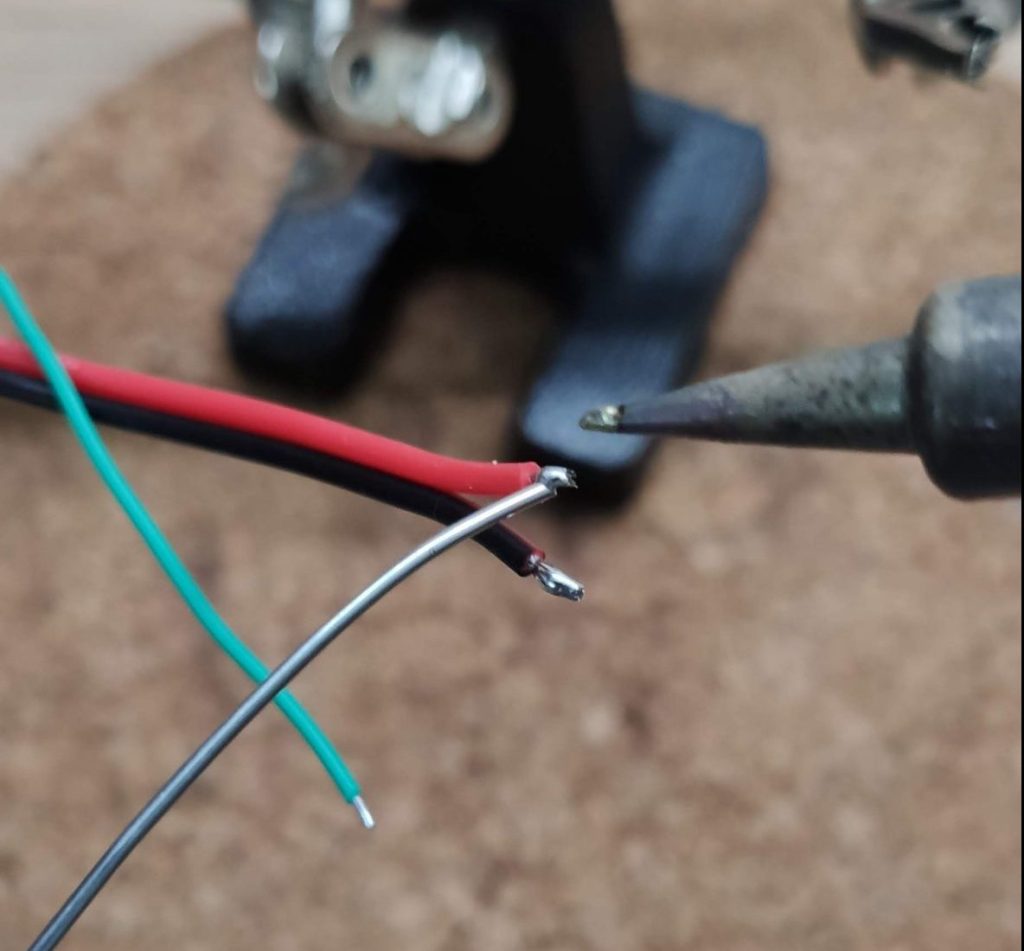
I started with the battery and soldered the wires to it. If you’re like me, add some electrical tape for extra safety.
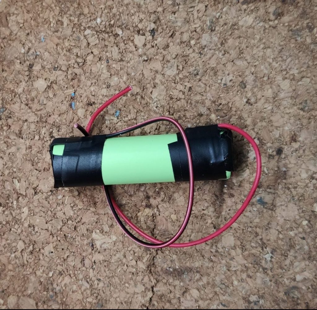
After that, I cut the positive wire in half, added heatshrinks and soldered the switch to the wire.

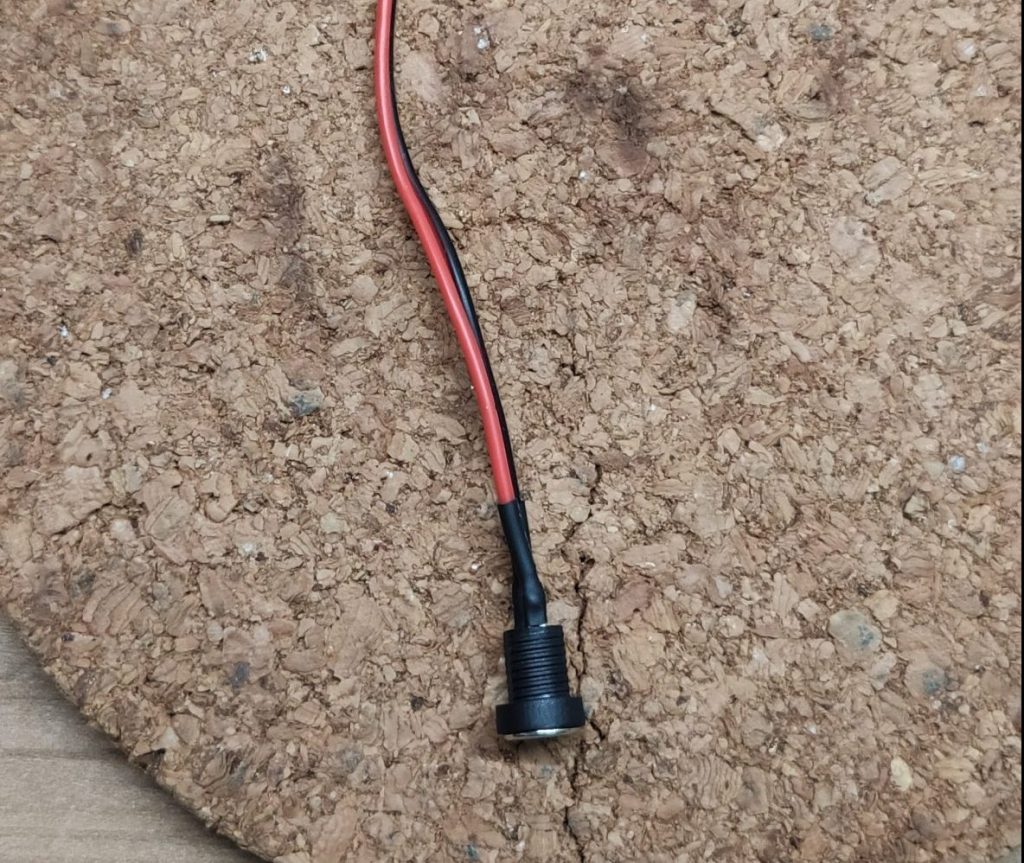
To complete the “power unit” I added the USB-C charging unit to the battery by soldering the wires to the battery pads on the circuit board.

Move on to the transistor circuit
Then I moved to the tricky part. Even if the circuit looks simple it kinda confused me during soldering, so I had my tinkercad circuit next to me and double checked every wire if I had to add a hearshrink or not.
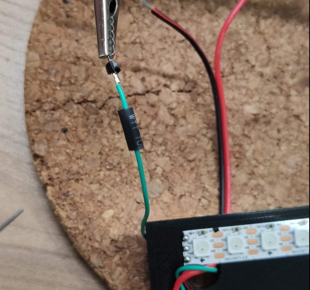
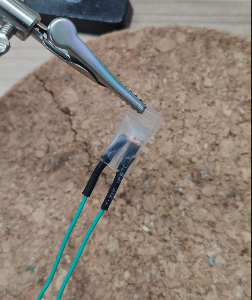
With that preparation I continued soldering wires to the LDR. Because it will be exposed to the weather, I added some transparent heatshrink to protect the LDR from the rain.
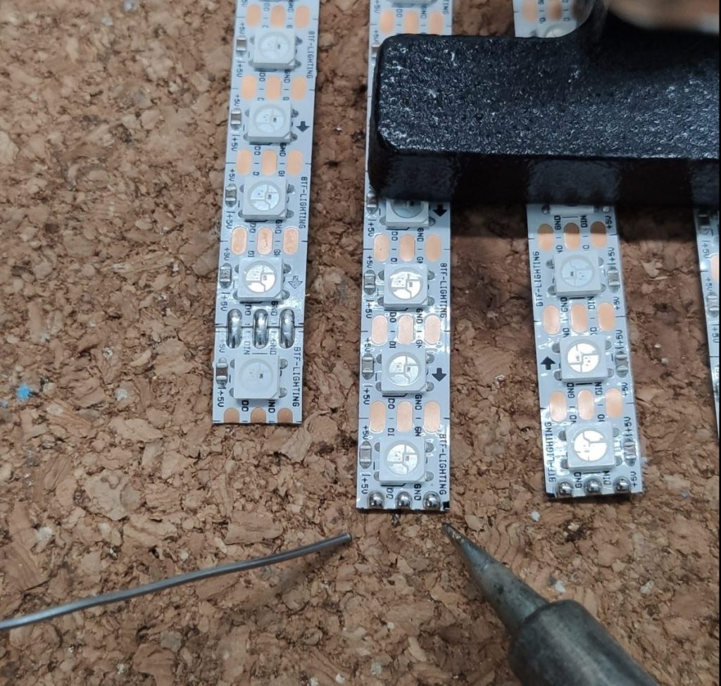
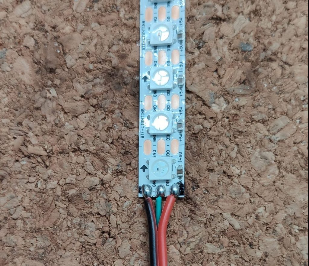
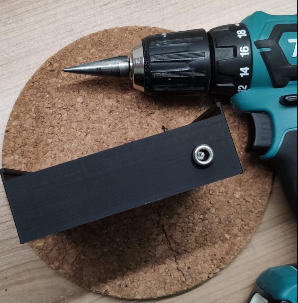
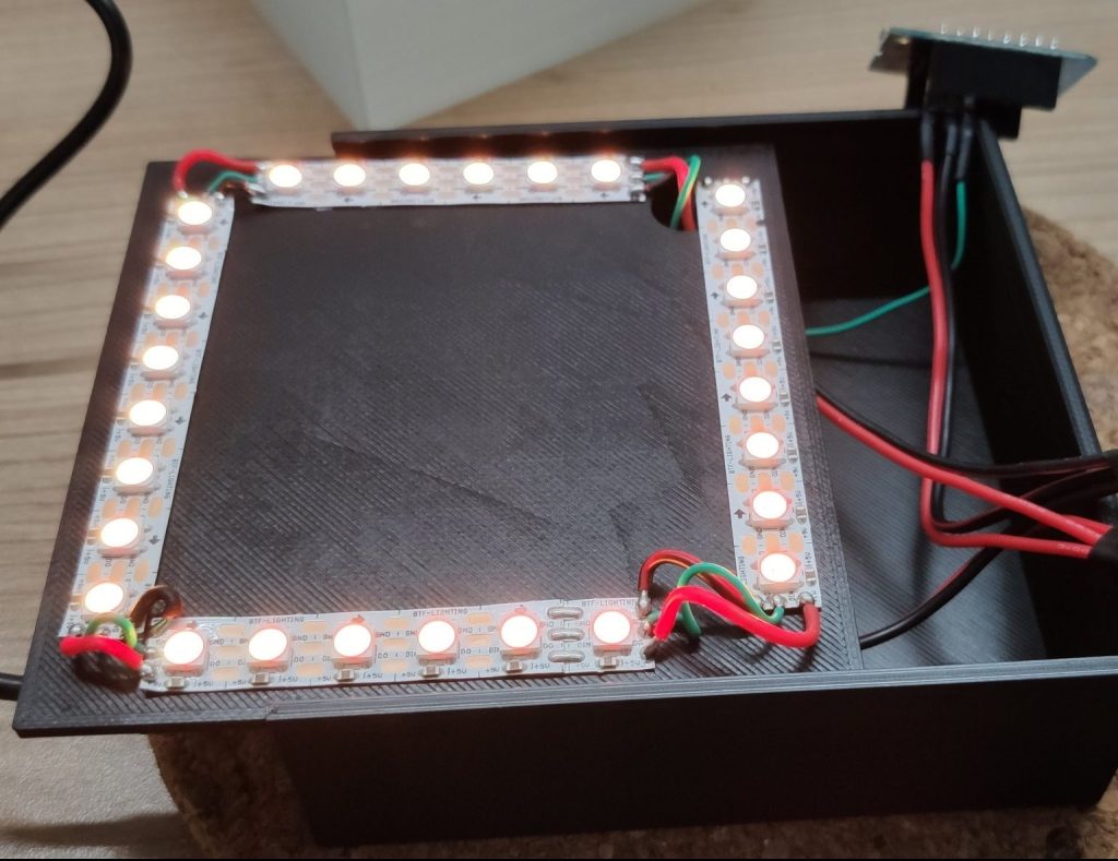
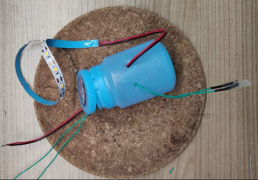
After that step I soldered some wires to the LED strip and drilled two holes in my enclosure to put the wires from the strip and LDR trough it. It’s important to do that before soldering the other components to the wires! Trust me, I did that mistake about 100 times 😄.
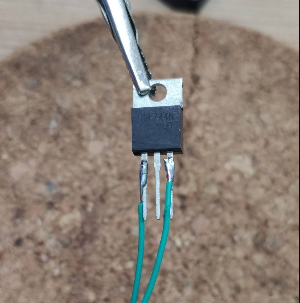
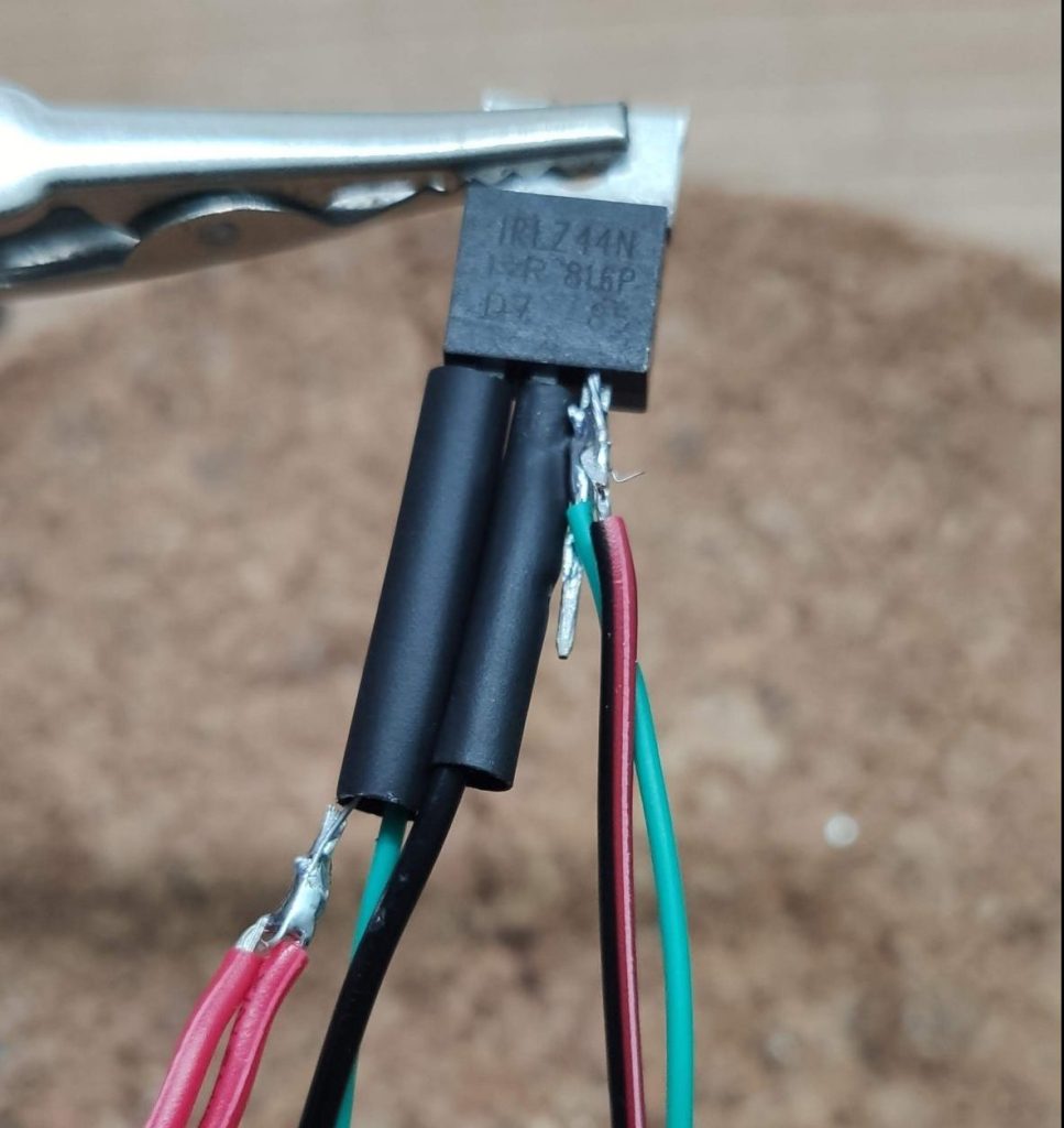
With my tinkercad drawing next to me I added heatshrinks to the LDR wires and soldered them to the gate (left pin) and the source (right pin) of the MOSFET.
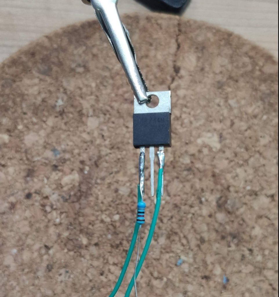
To create the voltage divider I added the 86K resistor to the gate (left pin) of the MOSFET.
Then I soldered the negative LED strip wire to drain (center pin) of the MOSFET. Same as before, don’t forget the heatshrink 😉.
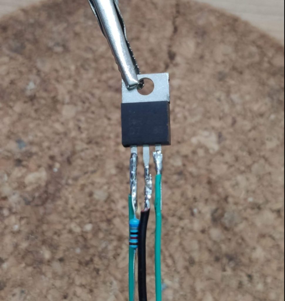
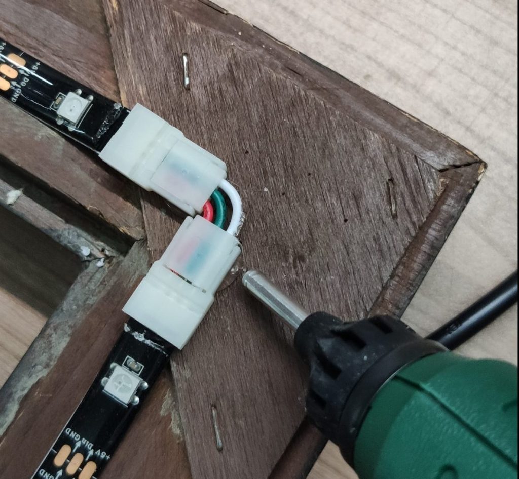
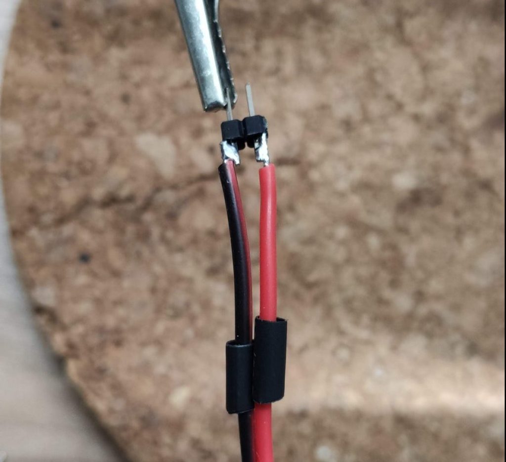
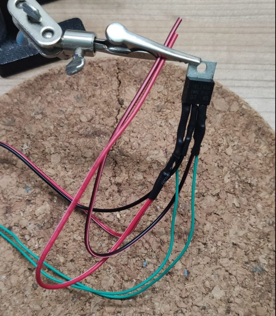
To create a connection for the “power unit” I cut off a piece of wire and soldered it to the positive wire of the LED strip. Then I slid a heatshrink over the two wires and moved the heatshrink from the LDR up to the MOSFET before I soldered the two wires to the resistor.
Almost done
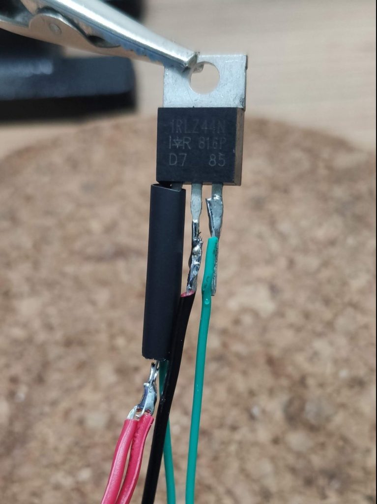
After finishing the voltage divider I slid up the heatshrink from the drain of the MOSFET and soldered a negative spare wire to the source of the MOSFET. This wire will be also connected to the “power unit”.
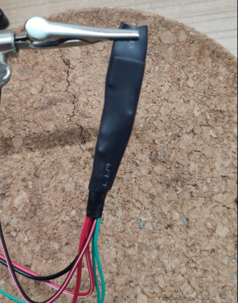
In the last step I secured all connections, heated up all heatshrinks and added a big one which fit over the MOSFET. So I ended up with a nice little package.
The final steps
To complete the wiring I soldered the two spare wires from the MOSFET to the “power unit”.

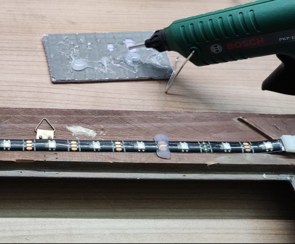
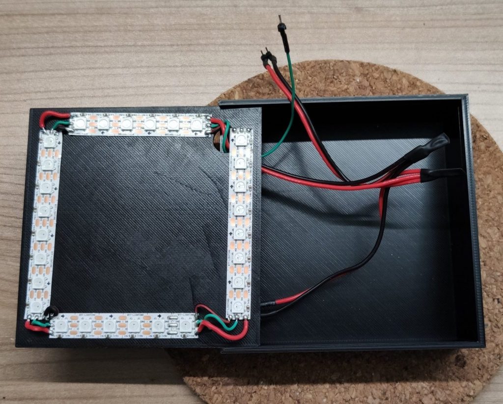
Now it was time to put everything into the enclosure and wrap the LED strip into the transparent heat shrink. Last not least I added some hot glue to the holes of the enclosure to prevent moisture inside the pumpkin 🎃.

Sum up
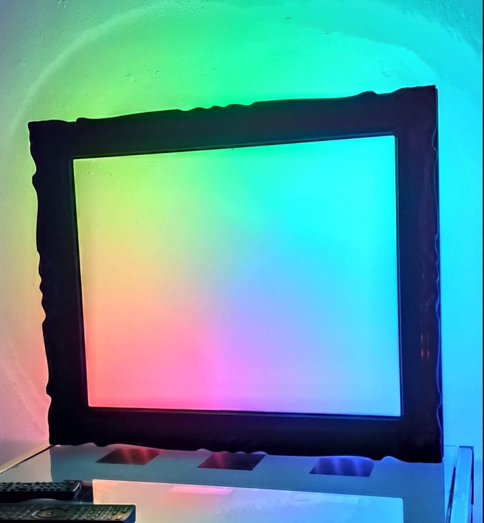
And that’s it, the automatic Halloween pumpkin light is done🎉. If you turn on the switch and cover the LDR with your hand, the LED strip starts to light up.
This was a really fun project; from the idea to tinkercad over to the breadboard till the final soldered result.
As always, if you like this project feel free to share it. If you have any questions, just write a comment or ping me on twitter 🐦.